Technological Education Resources Technological Education Resources Tech Edu
  • Educator Resources
    • General Slides
    • General Materials
    • General Design & Fabrication
    • Computer Engineering Notes
  • Classes
    • TAS Slides
    • TEJ Slides
    • TTJ / TTS Slides
  • Glossary
  • Lore
  • About
  1. 7. Laser Cutting and Fabrication Tools
  • General Design & Fabrication Home
  • 1. Culture and Land-Based Learning
    • 1. Grandmother Moon, Seasons, and Turtle’s Back
    • 2. Land Lettermark
  • 2. S.O. N.I.C.E. Design Process
    • 1. Understand the Situation & Opportunity
    • 2. Record User Needs
    • 3. Necessities and Nice-to-Haves
    • 4. Rank Priorities
    • 5. Investigate and Inquire
    • 6. Create and Communicate
    • 7. Evaluate and Repeat
  • 3. Emotions and Visual Communication
    • 1. Fear and Anxiety
    • 2. Anger
    • 3. Disgust
    • 4. Envy
    • 5. Jealousy
    • 6. Guilt
    • 7. Shame
    • 8. Happiness
    • 9. Love
    • 10. Sadness
  • 4. Logo Design in Photopea
    • 1. Build the Nameplate Text
    • 2. Warm-Up: Trace the AA Logo
    • 3. Trace a Multi-Layer Logo
    • 4. Combine Logo and Nameplate
    • 5. Design Your Own Name Tag
  • 5. Logo Animation
    • 1. Bring Your Brand to Life: Animate Your Logo
  • 6. Accessible Design
    • 1. Access and Alt Text
    • 2. Fonts and Text Effects
    • 3. Understanding Colour
    • 4. Contrast and Output
  • 7. Laser Cutting and Fabrication Tools
    • 1. Make It Stand
    • 2. Measure and Place
    • 3. Material Fit and Calibration
    • 4. Assemblies and Hybrid Fabrication
    • 5. Laser-Cut Assembly, Adhesives & Finishing
    • 6. Wall and Bench Tool Module
    • 7. Design and Fabrication Capstone
  • 8. Making the Phone Holder
    • 1. Choose Your Phone Holder
    • 2. CAD You Need
    • 3. Tools and Machines
    • 4. Build Steps
  • 9. Advanced Making: Stamp or Faux-Enamel Jewellery
    • 1. Mission 2: Logo Stamp
    • 2. Tinkercad Logo Stamp
    • 3. Onshape Logo Stamp
    • 4. Mission 3: Tinkercad Faux-Enamel Brooch
    • 5. Onshape Faux-Enamel Jewellery
  • CAD Tools
    • Fabrication Plate Builder
    • Laser-Cut Leg & Support Builder
    • Tool Organizer Gallery
  • Laser-Cutting Files and Resources

Laser-Cutting Ideas & Tools

See an idea, open a starting point, measure the real object, and make your own version.

A visual gallery of tool-organizer ideas, two fabrication builders, and reusable SVG starting points.

← General Design & Fabrication

Technology Commons · Tool organizer gallery

Browse organizer ideas and reusable parts. The Plate Builder and Leg & Support Builder are the two current interactive tools. The SVG catalogue provides starting points, not finished plans.

Open the laser-cut gallery Open the organizer guide Plate Builder Leg & Support Builder Browse SVGs
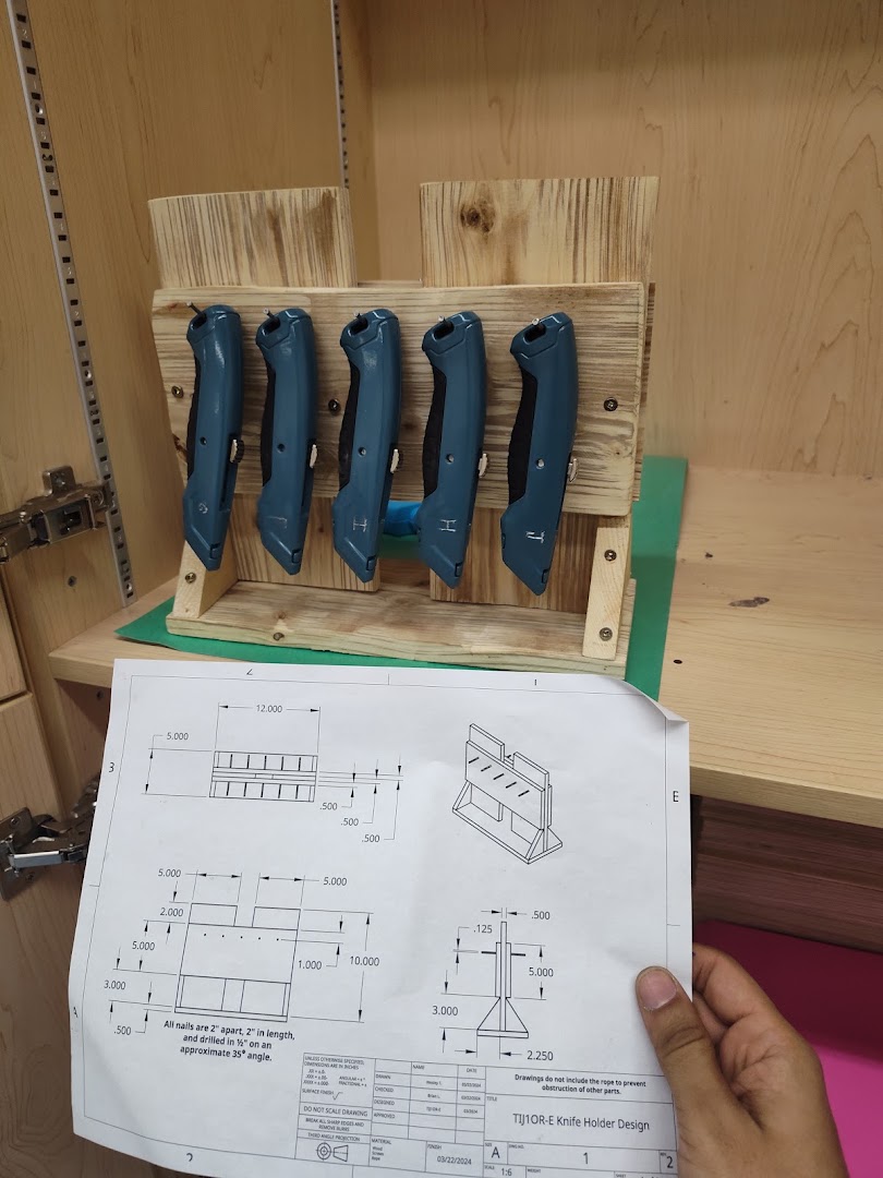
Freestanding wooden holder with five utility knives spaced so every handle can be seen and gripped.

Finished example

Portable utility-knife organizer

See the full annotated photo, orthographic drawing, spacing decisions, and documented revisions.

Study the example →
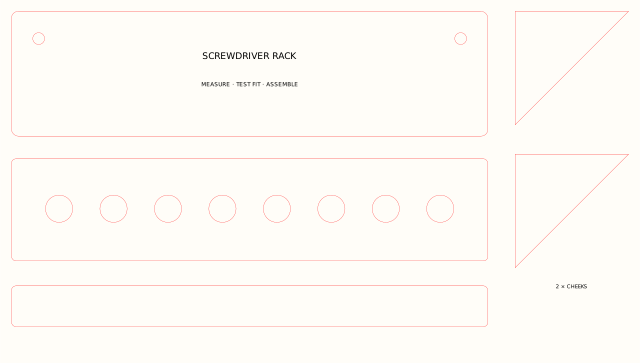
Laser-cut screwdriver rack kit shown as flat SVG parts.

Organizer idea

Screwdriver rack

Use the SVG as a visual starting point, then change the holes and spacing for the real tools.

Browse holder SVGs →
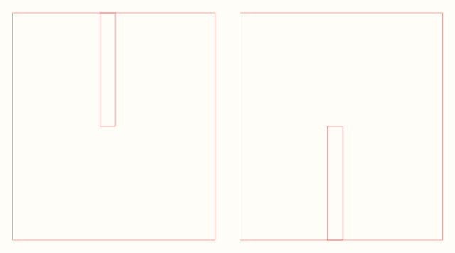
Two interlocking laser-cut parts form a cross stand.

Interactive tool

Legs and supports

Create a stand or support after measuring the project and the actual sheet material.

Open the builder →
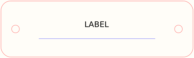
Simple rectangular laser-cut plate with rounded corners and mounting holes.

Interactive tool

Plates and hole patterns

Create a measured plate, ring, or repeated holder-hole pattern.

Open the builder →

SVG starting points

Browse the idea gallery

Use the pictures to find a useful part or organizer idea. Measure the real tools and material before cutting.

Filters 0

Filters narrow the current search. Preset buttons above always start a fresh view.

Loading catalogue…

No assets match this combination. Try clearing a filter.

Primary editor

Inkscape checklist

  1. Open the SVG at 100%; do not scale on import.
  2. Confirm document and display units are millimetres.
  3. Measure a known feature with the Measure tool.
  4. Inspect CUT (red), SCORE (blue) and ENGRAVE (black) geometry.
  5. Remove overlapping lines after combining or duplicating shapes.
  6. Save an editable copy and run a small physical test.

Text is not used for structural geometry. If engraved typography must look exact on another computer, convert a copy to paths after editing.

Parametric browser option

Veccy: change variables, not copies

Use the curated recipes for circles, rings, slots, fit gauges, module faces, racks, frames, stands and joinery. Define meaningful variables such as material_thickness, clearance, count, diameter, spacing, width and height, then reference them in feature expressions.

Open Veccy View 20 recipes

Export SVG, open it in Inkscape, confirm millimetres and physical size, then test-cut. Vectorpea is a compatibility target, not the primary workflow.

Physical verification

First shop test batch

Cut the dimension sheet, circle/hole tests, fit gauge, one French-cleat sample, one removable holder, one stand and one joint. Record stock measurements, machine settings, actual dimensions, selected fit, assembly result and changes. Only then advance an asset from unverified to dimension-tested, fit-tested or shop-tested.

Website code: AGPL 3.0. Educational content: CC BY-SA 4.0.

Educational content may be shared, copied, modified, and redistributed. Keep the CC BY-SA 4.0 licence and credit Andrew Andrade, andrewandrade.ca, and github.com/mrandrewandrade. Add your own name and links when adapting it. Sharing is caring.

The website code uses the AGPL 3.0, a copyleft licence: if you share modified code or run a modified version as a network service, you must make the corresponding source code available under the same licence.

 
  • References

  • Licensing