Laser Cutter Calibration | Material Thickness, Kerf & Fit Tests
Calibration is not one magic kerf value. It is a short, recorded test that connects this sheet, this machine condition, this geometry, and this intended fit.
Operating procedure or material calibration?
Operating procedure
Machine-specific setup, safety instruction, assessments, and authorization are not provided on this public website. Follow your school board’s safety guidelines and the course-specific instruction provided by your teacher. Students in Mr. Andrade’s classes can find that information in Google Classroom.
Material calibration
Measure how one stock-and-setting combination changes size and fit. This is about the result of the process.
- Actual thickness and batch are recorded.
- A known drawing dimension imports at 100%.
- Cut width and finished dimensions are measured.
- Slots and holes are tested against the real mating object.
1 · Measure the actual sheet
Plywood sold as 1/4 inch may not measure 6.35 mm. Measure at several locations with callipers, including near a visibly damaged edge but not on it. Record the minimum, maximum and the value used to design the test.
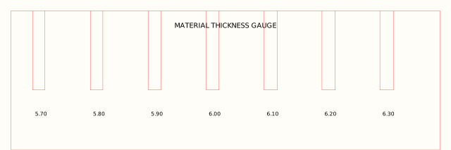 Material thickness
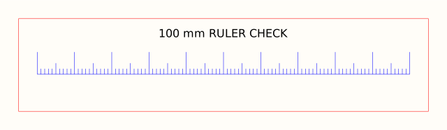 Ruler / scale check
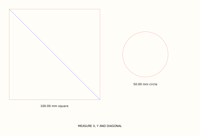 Dimension verification
2 · Understand what kerf changes
The beam removes a narrow band centred on the path. With the path drawn on the intended boundary, an outside part tends to finish smaller and an inside opening tends to finish larger. The magnitude varies, so do not copy a universal number.
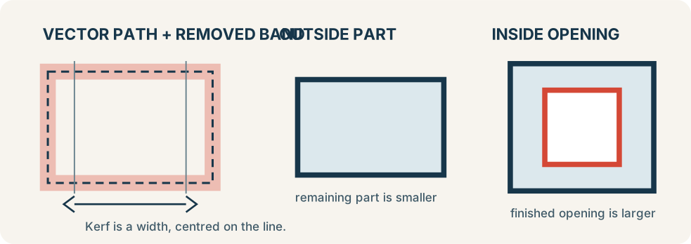
BRM’s current kerf and kerf-compensation explanation is a useful process reference. BRM also hosts a free kerf gauge SVG, credited there to Nameek and Elplatt, and explicitly tells users to check scale after import. Use it as another test method, not as a pre-approved local setting.
Ponoko’s 2011 article, Figuring out kerf for precision parts, is included only as a historical/conceptual example of test-and-revise thinking. Do not copy its old settings or service-specific assumptions.
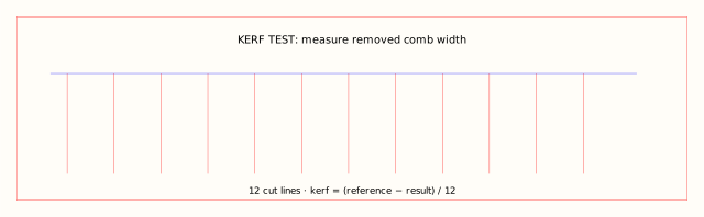 Kerf testMeasure a repeated cut rather than guessing from one edge.
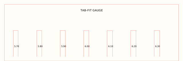 Tab fitTest the male feature and its orientation.
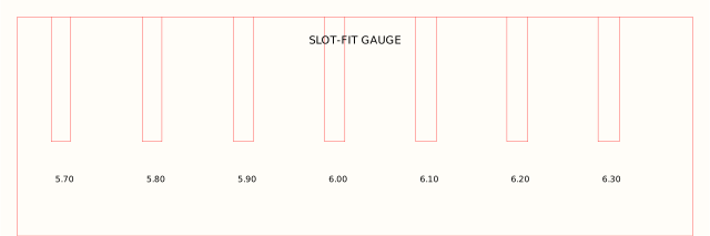 Slot fitStart from measured thickness, then compare a small series.
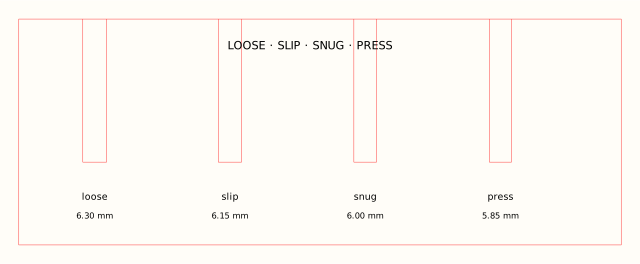 Four-fit seriesName the function: loose, sliding, snug or press.
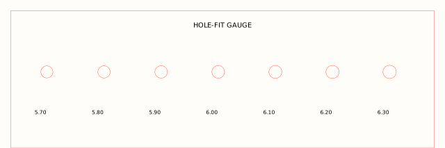 Hole fitTest the actual bottle, dowel or fastener, not only a calliper.
3 · Cut, measure and decide
- Open one test SVG in Inkscape and confirm document units,
viewBoxscale and a known dimension. - Label the coupon with material, batch, date, machine and revision before cutting.
- Use the course-specific process provided by your teacher.
- Let the coupon cool and measure it consistently; do not force a calliper into a soft or angled edge.
- Test the real mating object in every candidate feature.
- Select the fit that serves the function. A press fit is not automatically “more accurate” than a sliding fit.
- Update the source dimension, save the record and repeat only the smallest necessary test.
Kerf compensation changes geometry; it does not correct a machine-condition problem, warped stock, or an incorrectly scaled import. Resolve unexpected machine behaviour through the course-specific process before interpreting the coupon.
Printable calibration record
Technology Commons · Laser calibration record
Name / group
Date
Machine
File + revision
Material / batch
Nominal thickness
Measured min / max
Drawing scale checked with
Course process reference
Calibration revision
| Feature / nominal | Measured result | Real-object fit | Decision / next revision |
|---|---|---|---|
Selected fit and why
Observed issues / follow-up
Tester / instructor review
Open the complete calibration library for downloadable source files.
Ontario curriculum relevance: Strongly relevant to TMJ2O Manufacturing Technology, TDJ2O, and TIJ1O, with applications in TCJ2O, TEJ2O, and senior manufacturing/design courses involving measurement, tolerance, process control, quality, jigs, fixtures, and CAD/CAM.
Next: apply the recorded dimensions in Assemblies + Hybrid Fabrication, the Fabrication Plate Builder, or your own Inkscape source.