Technological Education Resources Technological Education Resources Tech Edu
  • Educator Resources
    • General Slides
    • General Materials
    • General Design & Fabrication
    • Computer Engineering Notes
  • Classes
    • TAS Slides
    • TEJ Slides
    • TTJ / TTS Slides
  • Glossary
  • Lore
  • About
  1. Pill-Bottle Organizer | Five Reference Assemblies
  • General Design & Fabrication Home
  • 1. Culture and Land-Based Learning
    • 1. Grandmother Moon, Seasons, and Turtle’s Back
    • 2. Land Lettermark
  • 2. S.O. N.I.C.E. Design Process
    • 1. Understand the Situation & Opportunity
    • 2. Record User Needs
    • 3. Necessities and Nice-to-Haves
    • 4. Rank Priorities
    • 5. Investigate and Inquire
    • 6. Create and Communicate
    • 7. Evaluate and Repeat
  • 3. Emotions and Visual Communication
    • 1. Fear and Anxiety
    • 2. Anger
    • 3. Disgust
    • 4. Envy
    • 5. Jealousy
    • 6. Guilt
    • 7. Shame
    • 8. Happiness
    • 9. Love
    • 10. Sadness
  • 4. Logo Design in Photopea
    • 1. Build the Nameplate Text
    • 2. Warm-Up: Trace the AA Logo
    • 3. Trace a Multi-Layer Logo
    • 4. Combine Logo and Nameplate
    • 5. Design Your Own Name Tag
  • 5. Logo Animation
    • 1. Bring Your Brand to Life: Animate Your Logo
  • 6. Accessible Design
    • 1. Access and Alt Text
    • 2. Fonts and Text Effects
    • 3. Understanding Colour
    • 4. Contrast and Output
  • 7. Laser Cutting and Fabrication Tools
    • 1. Make It Stand
    • 2. Measure and Place
    • 3. Material Fit and Calibration
    • 4. Assemblies and Hybrid Fabrication
    • 5. Laser-Cut Assembly, Adhesives & Finishing
    • 6. Wall and Bench Tool Module
    • 7. Design and Fabrication Capstone
  • 8. Making the Phone Holder
    • 1. Choose Your Phone Holder
    • 2. CAD You Need
    • 3. Tools and Machines
    • 4. Build Steps
  • 9. Advanced Making: Stamp or Faux-Enamel Jewellery
    • 1. Mission 2: Logo Stamp
    • 2. Tinkercad Logo Stamp
    • 3. Onshape Logo Stamp
    • 4. Mission 3: Tinkercad Faux-Enamel Brooch
    • 5. Onshape Faux-Enamel Jewellery
  • CAD Tools
    • Fabrication Plate Builder
    • Laser-Cut Leg & Support Builder
    • Tool Organizer Gallery
  • Laser-Cutting Files and Resources

On this page

  • Design problem
  • See and compare the five assemblies
  • Bill-of-material and parameter routine
  • Physical-test record
  • Reference systems worth studying

Pill-Bottle Organizer | Five Reference Assemblies

Configurable laser-cut pill-bottle organizer references for auto-shop organization, with parts, exploded diagrams, BOMs, measured parameters and honest test status.
Simple shelf rack previewA Simple shelf Dowel-supported rack previewB Dowel-supported Reinforced wall rack previewC Reinforced wall Removable wall and bench rack previewD Wall / bench Captured bottle rack with removable keeper previewE Captured bottles

Download all five assemblies + classroom files (ZIP) View dimensions, BOMs + status (JSON)

Design problem

Create an organizer for labelled shop pill bottles used to separate small fasteners or parts. The organizer should make contents visible, bottles easy to return and the storage location predictable. Measure the actual classroom bottles. The downloadable files use a documented example: 34 mm body, 42 mm cap, 36 mm opening and 42 mm centre spacing.

The 36 mm opening allows the example body to pass through while the larger cap retains the bottle. That is a hypothesis to test, not a universal bottle size. Cut one opening coupon before a complete rack.

Use the Fabrication Plate Builder to regenerate a measured row or grid, then follow Material Fit + Calibration before committing a full sheet.

See and compare the five assemblies

ImportantIdeas, not answers

These assemblies are deliberately different starting points. They show load paths, interfaces and service ideas; they do not tell you which organizer your space needs. Measure the bottles and the work area, select useful principles, then make and record your own tested revision.

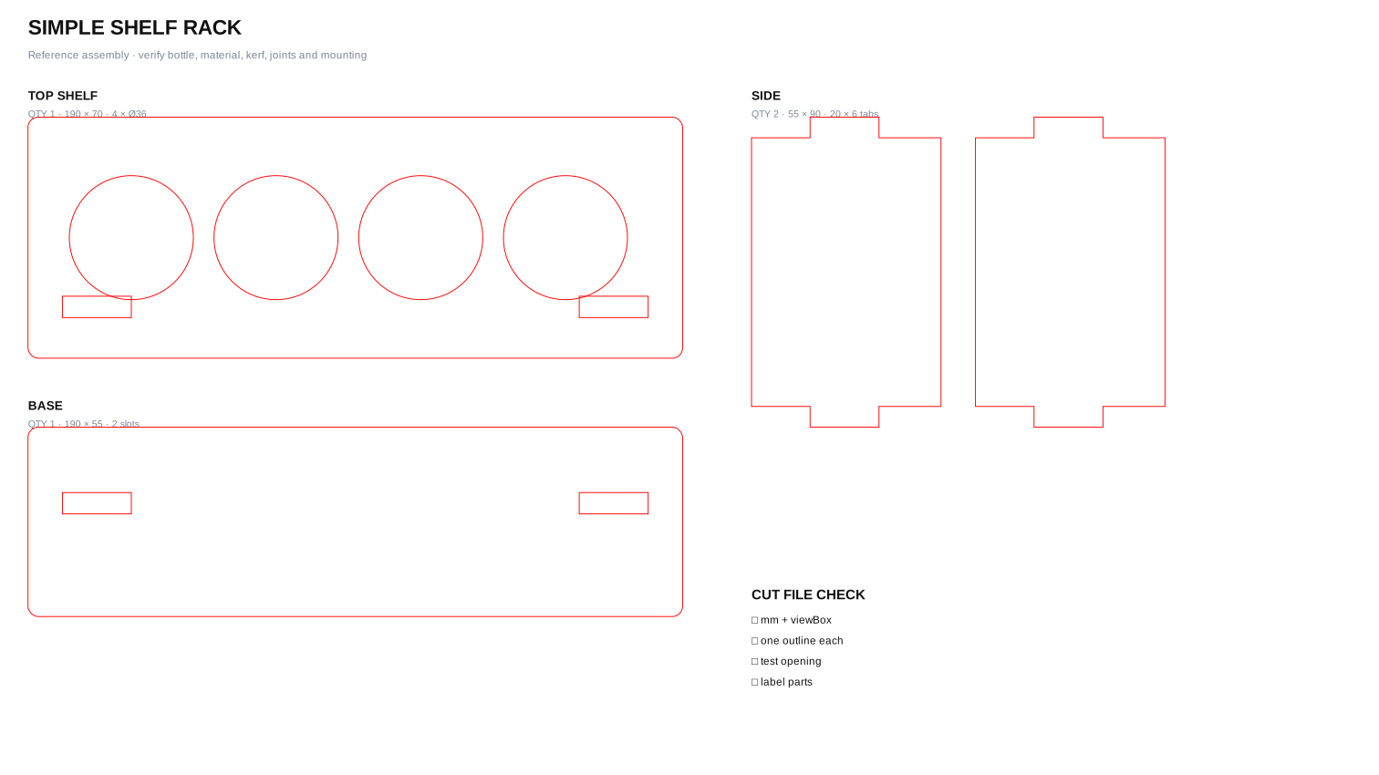
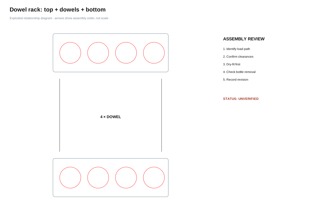
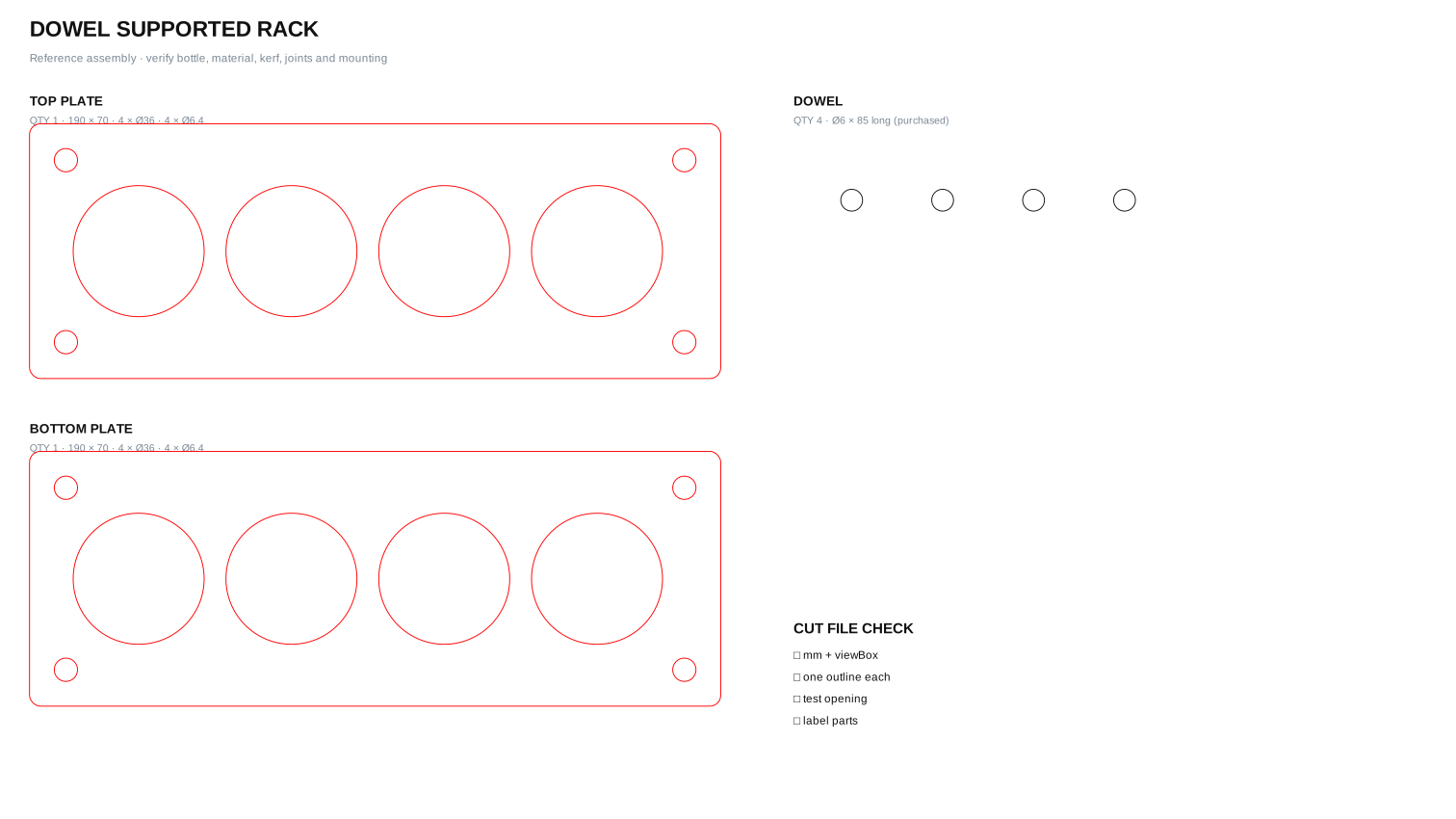
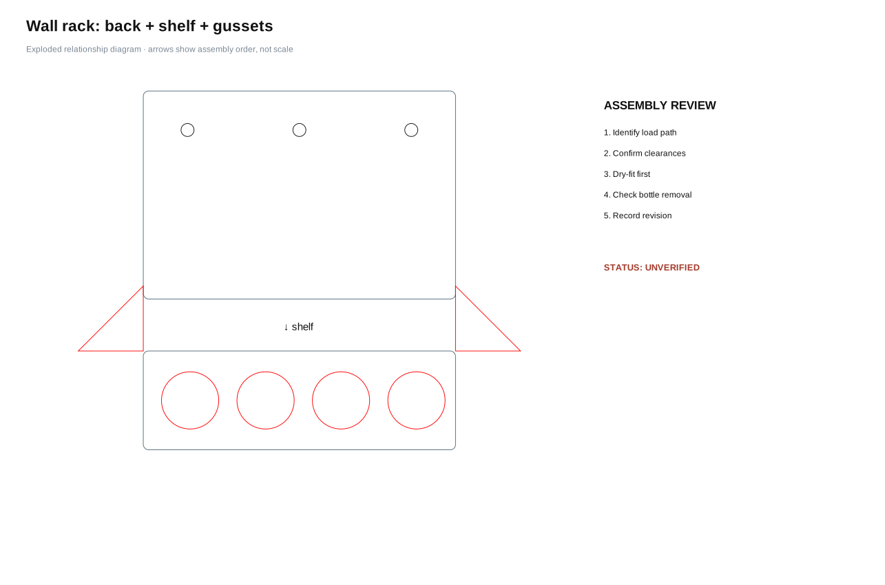
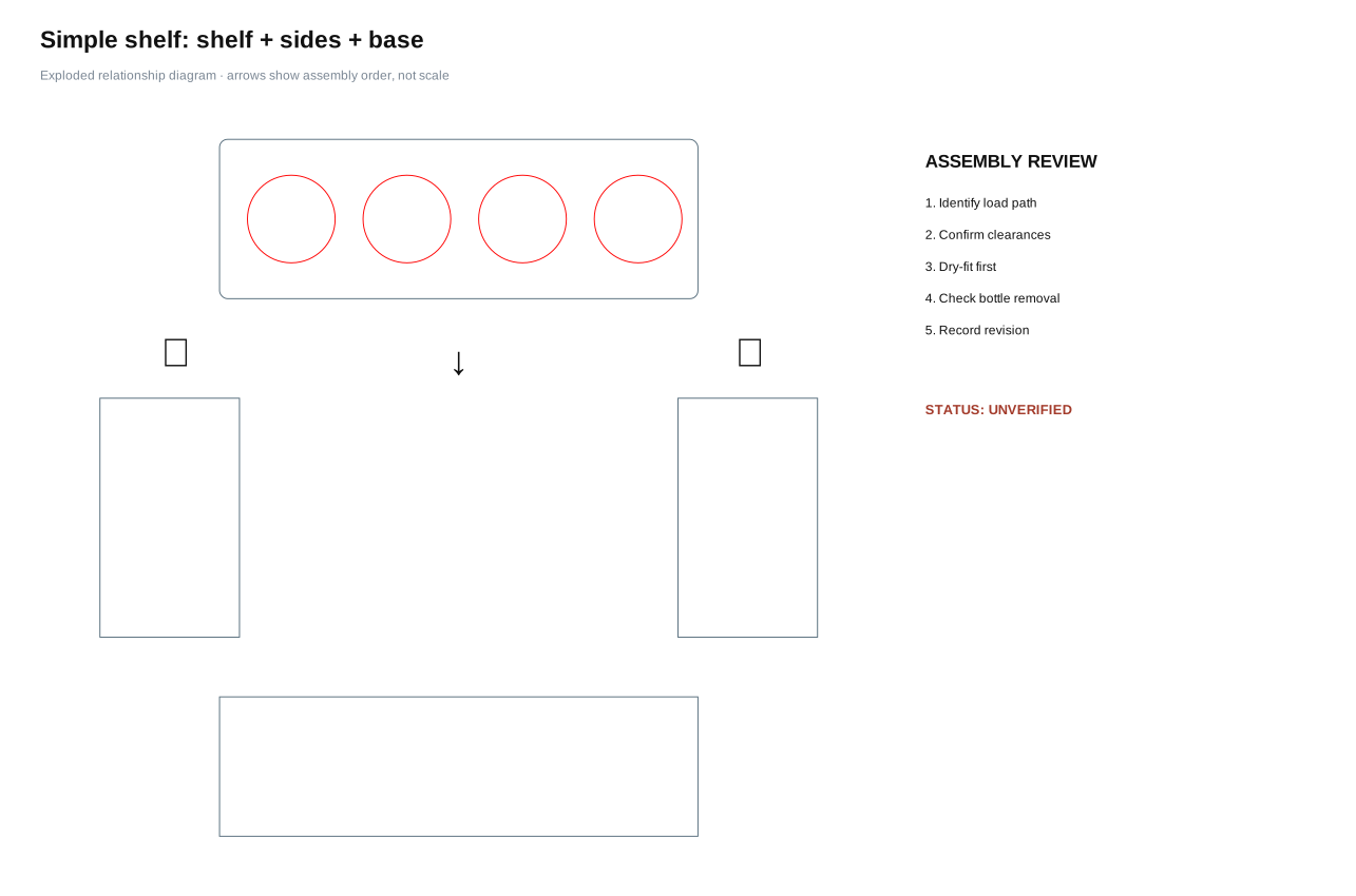
Each card shows both files you receive: the exploded view explains how the assembly goes together; the parts sheet is the true-size SVG students adapt in Inkscape. Select either preview to open it full size.

Exploded view of the simple shelf rackExploded assembly

A · Best first build

Simple shelf rack

Four laser-cut parts create the clearest load path: a perforated shelf, base and two tabbed sides.

Location
Bench
Parts
4
New idea
Tabs + slots
True-size cutting parts for the simple shelf rackTrue-size parts sheet
Download parts SVGOpen exploded SVG

Test: Is the shelf high enough to retain bottles but low enough for an easy lift?

Exploded view of the dowel-supported rackExploded assembly

B · Hybrid fabrication

Dowel-supported rack

Two laser-cut plates are separated and aligned by four purchased dowels.

Location
Bench
Parts
2 cut + 4 dowels
New idea
Hole allowance
True-size cutting parts for the dowel-supported rackTrue-size parts sheet
Download parts SVGOpen exploded SVG

Test: What dowel-hole allowance gives alignment without wobble?

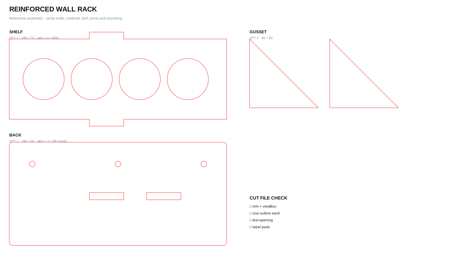
Exploded view of the reinforced wall rackExploded assembly

C · Load path study

Reinforced wall rack

A tabbed shelf meets a back plate; two gussets reinforce the joint. Wall hardware remains site-specific.

Location
Wall
Parts
4 + fasteners
New idea
Gussets + anchors
True-size cutting parts for the reinforced wall rackTrue-size parts sheet
Download parts SVGOpen exploded SVG

Test: Which approved wall, anchor and fastener system carries the complete load?

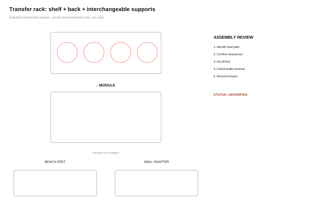
Exploded view of the removable wall and bench rackExploded assembly

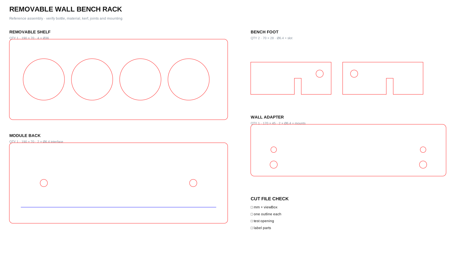
D · Transferable module

Removable wall / bench rack

The same organizer body registers to either two bench feet or an approved wall adapter using two M6 hand knobs.

Location
Wall or bench
Parts
5 + hardware
New idea
Shared interface
True-size cutting parts for the removable wall and bench rackTrue-size parts sheet
Download parts SVGOpen exploded SVG

Test: Is the transfer interface obvious, stable and impossible to install backwards?

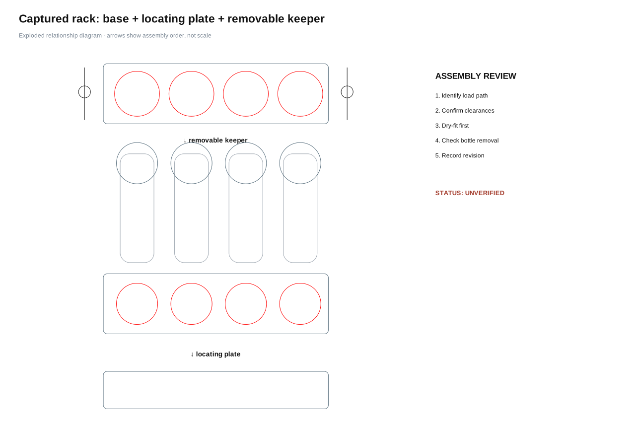
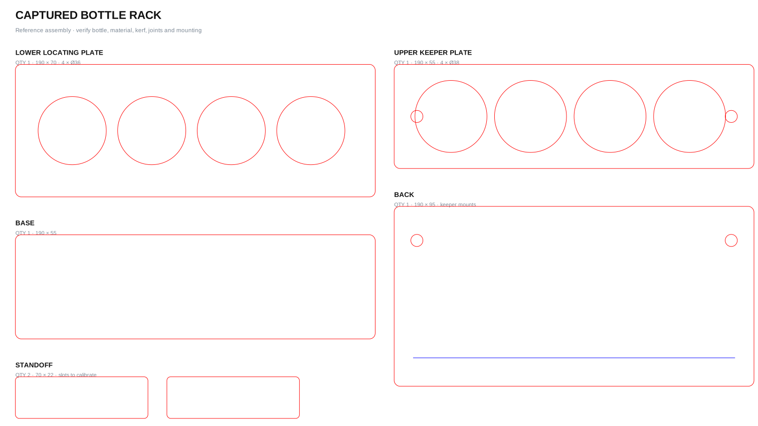
Exploded view showing bottles between a lower locating plate and removable upper keeper plateExploded assembly

E · Serviceable retention

Captured bottle rack

A lower plate locates each bottle body. A hand-knob-retained upper plate sits below the wider cap shoulder, resisting accidental lift while remaining removable for service.

Location
Bench / approved wall
Parts
6 cut + hardware
New idea
Removable keeper
True-size cutting parts for the captured bottle rackTrue-size parts sheet
Download parts SVGOpen exploded SVG

Service sequence: Support bottles → remove two knobs → lift keeper → replace bottles → refit keeper and knobs → record the revision.

Status: physically unverified. The keeper is not a child-resistant lock.

NoteWhat the downloads contain
  • Parts SVG: true-size geometry in millimetres for editing, measuring and test cutting in Inkscape.
  • Exploded SVG: assembly order and part relationships for discussion or projection.
  • Assembly manifest: BOM, starting dimensions, interfaces, service record fields and physical-test status for all five systems.
  • Complete ZIP: every organizer file plus the palettes, name-tag resources and individual components.

Bill-of-material and parameter routine

For any selected reference:

  1. Measure at least three bottles: body diameter, cap diameter, height and any taper.
  2. Choose the controlling diameter and required radial clearance.
  3. Calculate opening = largest measured body + 2 × radial clearance.
  4. Set centre spacing from cap diameter, hand access and remaining material, not appearance alone.
  5. Update part dimensions and BOM before nesting.
  6. Cut an opening coupon, record actual fit, then revise the source.
  7. Dry-assemble; test insertion, removal, labels, tipping and collisions.

Physical-test record

All five files currently have status unverified. Do not change that label because the SVG opens correctly. Record the material, measured thickness, machine, settings reference, date, tester, actual opening, fit result, load and revision before promoting a design to fit-tested or shop-tested.

Reference systems worth studying

The sketches below are original Technology Commons diagrams, not copied product images. Follow each source to inspect the actual system and its licence. Borrow a principle only after checking dimensions, load, access, fabrication method and the source’s current terms.

French cleat

Principle: a continuous angled interface makes modules movable while the lower stand-off controls tilt.

Adapt: add an anti-lift or anti-slide feature where impact is possible.

Source: Wikipedia contributors · page content CC BY-SA · reference link · original schematic here is AGPL-3.0 · reference only

Gridfinity

Principle: a shared pitch lets containers move without redesigning the whole storage field.

Adapt: use a consistent centre spacing or interface datum across shop modules.

Source: Zack Freedman / Voidstar Lab and Kenneth Hodson’s rebuild · MIT · reference link · original schematic AGPL-3.0 · reference only

openGrid

Principle: a regular wall field separates the mounting interface from each accessory.

Adapt: document one interface and test light- and heavy-duty versions separately.

Source: David D / openGrid contributors · core parts CC BY · reference link · original schematic AGPL-3.0 · reference only

Pegstr

Principle: parametric holders begin with the object and the host-board standard.

Adapt: measure both; do not assume imported inch pegboard dimensions match local stock.

Source: MGX3D · CC BY-NC · reference link · original schematic AGPL-3.0 · reference only

5S shadow board

Principle: a visible home position makes missing or misplaced items obvious.

Adapt: labels and silhouettes should support return, counting and inspection, not decoration.

Source: National Highways visual-management standard · Crown publication, linked for reference; no source media reused · reference link · original schematic AGPL-3.0 · reference only

Flexible fabrication workshop

Principle: organize around workflow, shared infrastructure and reconfigurable work zones.

Adapt: map where material arrives, work happens, parts wait and completed work leaves.

Source: Open Source Ecology contributors · open-source project; linked page terms govern reuse and no source media is copied · reference link · original schematic AGPL-3.0 · reference only

Warning

Wall mounting is not a decorative SVG problem. The wall substrate, anchor, fastener, backer, load, impact and inspection routine must be approved by the responsible instructor. A laser-cut plate is not a rated anchor.
Website code: AGPL 3.0. Educational content: CC BY-SA 4.0.

Educational content may be shared, copied, modified, and redistributed. Keep the CC BY-SA 4.0 licence and credit Andrew Andrade, andrewandrade.ca, and github.com/mrandrewandrade. Add your own name and links when adapting it. Sharing is caring.

The website code uses the AGPL 3.0, a copyleft licence: if you share modified code or run a modified version as a network service, you must make the corresponding source code available under the same licence.

 
  • References

  • Licensing