Component Foundations 1: Circuits and Schematics
Learning goals
- I can explain what a circuit and a schematic are.
- I can identify a source, conductor, control, protection device, and load.
- I can recognize common component symbols without confusing them with physical appearance.
- I can trace one complete path and identify connected nodes.
What is a circuit?
A circuit is a set of connected electrical components that provides one or more paths for current. A useful circuit normally has:
- a source that supplies electrical energy;
- conductors that connect points;
- a control such as a switch;
- protection such as current limiting or a fuse;
- a load that converts electrical energy into light, motion, heat, sound, or another useful form.
A pile of components is not yet a circuit. Their connections determine what the system does.
What is a schematic?
A schematic is a functional map of electrical connections. It does not try to look like the physical breadboard or product. It preserves the information needed to understand the circuit:
- which terminals are connected;
- which components are used;
- component names and values;
- polarity and current direction when relevant;
- the chosen 0 V reference.
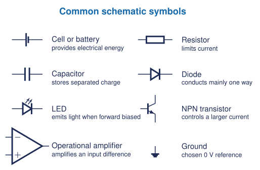
Lines, nodes, and junctions
A line normally represents a conductor. Every uninterrupted set of connected lines is one node, so all points on that node have the same ideal voltage.
- A visible dot marks a junction when several lines connect.
- Crossing lines without a junction dot should be treated as not connected unless the drawing standard states otherwise.
- Ground is the chosen 0 V reference for voltage measurements. It is not automatically the Earth.
- A component interrupts a wire because current must pass through that component between two nodes.
Read a first schematic
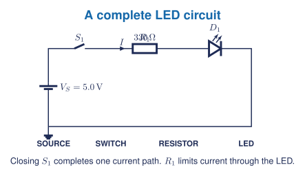
Trace from the positive source terminal through \(S_1\), \(R_1\), and \(D_1\), then back to the source through ground. The resistor is not optional decoration: it limits current to protect the LED.
Reference designators
Schematics give each component a short identifier.
| Prefix | Component | Example |
|---|---|---|
| R | resistor | R1 |
| C | capacitor | C1 |
| D | diode or LED | D1 |
| Q | transistor | Q1 |
| U | integrated circuit or functional block | U1 |
| S or SW | switch | S1 |
| V or BT | voltage source or battery | V1 or BT1 |
The number distinguishes components of the same type. It does not normally give the component value.
Five-question starter
- Identify the source, control, current limiter, and load in Figure 2.
- Explain why a schematic does not need to match the physical placement of parts.
- Redraw Figure 2 with the switch open and state whether a complete path exists.
- Mark the distinct nodes in Figure 2 and identify the node chosen as 0 V.
- A student removes \(R_1\) and replaces it with a wire. Explain why this is unsafe for the LED even though the path still looks complete.
Start-now activity
Before handling components, rebuild Figure 2 in a teacher-approved circuit simulator. Predict the current direction and the effect of opening the switch before starting the simulation. Record calculated, simulated, and measured evidence in separate columns.
Textbook and visual support
Grob provides the main circuit vocabulary and progression from quantities to components and connections. [1, Ch. 1] Open Circuits is a classroom visual reference for comparing the outside of a component with its internal construction. [2] Public diagrams on this page are original and do not reproduce the book’s cutaway images.