Capacitors 2: RC Charging and Discharging
Use the same time and voltage data from Tuesday’s handout. Calculate \(\tau=RC\), plot the measured values as dots, define the charging and discharging functions, and overlay their smooth curves. Then use KVL and a simple LED function to predict how the light fades as the capacitor discharges. The notebook supplies the exponential syntax and scaffolds the required changes.
This lesson uses a resistor to control how quickly a capacitor charges or discharges.
Charging
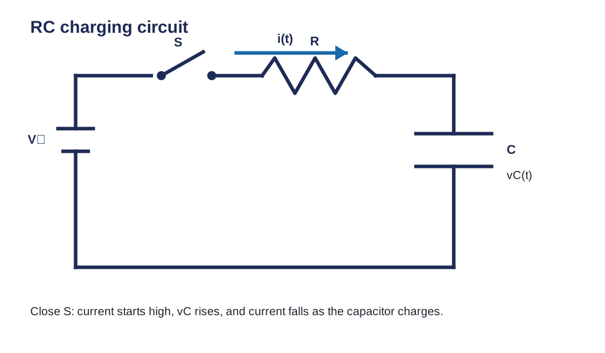
At the instant the switch closes for an ideal uncharged capacitor:
\[ v_C(0)=0\,\mathrm{V},\qquad i(0)=\frac{V_S}{R} \]
The current is largest at the start. As the capacitor voltage rises, the resistor voltage and current fall.
After a long time:
\[ v_C(\infty)=V_S,\qquad i(\infty)=0\,\mathrm{A} \]
The charged capacitor behaves like an open circuit for steady DC in this ideal model.
Discharging
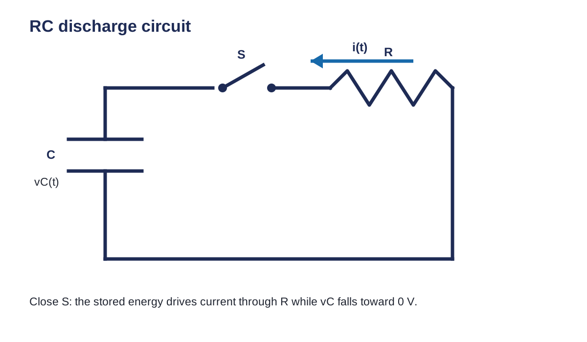
The capacitor voltage cannot jump instantly in the ideal model. It falls from its starting value toward \(0\,\mathrm{V}\).
Read the graph
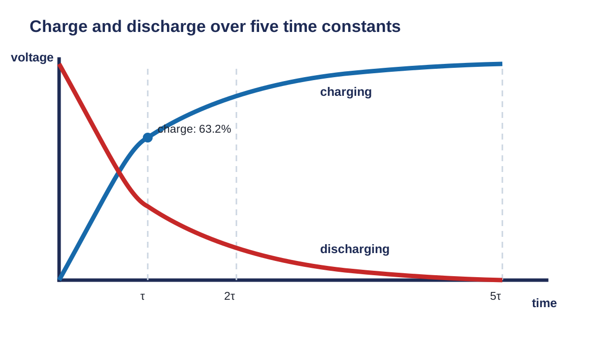
For charging toward a source voltage \(V_S\):
\[ v_C(\tau)\approx0.632V_S,\qquad v_C(5\tau)\approx0.993V_S \]
For discharging from \(V_0\):
\[ v_C(\tau)\approx0.368V_0,\qquad v_C(5\tau)\approx0.0067V_0 \]
Worked example using GUESS
A capacitor charges toward \(12.0\,\mathrm{V}\). Estimate its voltage after one time constant and after five time constants.
Given
\[V_S=12.0\,\mathrm{V},\qquad t=\tau\text{ and }5\tau\]
Unknown
\[v_C(\tau),\qquad v_C(5\tau)\]
Equations
\[v_C(\tau)\approx0.632V_S,qquad v_C(5\tau)\approx0.993V_S\]
Substitute and solve
\[ v_C(\tau)=0.632(12.0\,\mathrm{V})=7.58\,\mathrm{V} \]
\[ v_C(5\tau)=0.993(12.0\,\mathrm{V})=11.9\,\mathrm{V} \]
Statement
The capacitor is about \(7.58\,\mathrm{V}\) after one time constant and \(11.9\,\mathrm{V}\) after five time constants.
Tinkercad check
- Calculate the expected starting, one-time-constant, and five-time-constant values first.
- Build the source, switch, resistor, and capacitor in one loop.
- Use red for positive, black for \(0\,\mathrm{V}\), and another colour for the capacitor signal node.
- Place the voltmeter across the capacitor.
- Start the simulation, close the switch, and record the capacitor voltage.
- Share the Tinkercad circuit link.
Use the step-by-step Tinkercad circuit guide if you need the controls and screenshots.
Complete the work
- Complete all five questions using GUESS.
- Label \(0\), \(\tau\), and \(5\tau\) on the graph.
- Use the notebook to check the estimates.
- Build one charging circuit in Tinkercad.
- Submit the sheet, notebook, and Tinkercad link.
Textbook support: Grob, Chapter 22, sections 22-2 to 22-3, pp. 668-675. Practice support: Problems Manual, Chapter 22, pp. 309-316. Optional teacher-approved lab: Experiment 22-1. [1, Ch. 22]
Equation and diagram source files
Next lesson
Continue to RC Time Constants and Design.
Help improve this lesson
If a direction, diagram, simulation step, or code cell is unclear, identify the exact step. Explain what you tried and what happened.