Component Foundations 6: Operational Amplifiers
Learning goals
- I can identify the non-inverting input, inverting input, output, and supply rails.
- I can explain that an op-amp responds to the difference between its input voltages.
- I can trace negative feedback in a voltage follower.
- I can distinguish an ideal op-amp model from a real 741 or XL741.
What is an op-amp?
An operational amplifier, or op-amp, is a high-gain differential amplifier. Its basic relationship is:
\[V_{OUT}=A_{OL}(V_+-V_-)\]
\(V_+\) is the non-inverting input, \(V_-\) is the inverting input, and \(A_{OL}\) is open-loop gain. Because open-loop gain is very large, useful circuits normally apply feedback rather than operate the amplifier open loop.
An op-amp also needs power-supply connections. The triangle symbol often omits those rails to keep a schematic readable, but the physical circuit cannot operate without them.
Negative feedback and a voltage follower
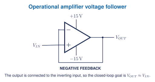
In the ideal negative-feedback model:
- input currents are approximately zero;
- the output moves so that \(V_+\approx V_-\) when the amplifier is operating normally;
- the output cannot exceed the available supply and output-swing limits.
These are model assumptions, not universal facts. They fail during saturation, excessive input difference, missing power, instability, wiring faults, or operation outside the datasheet.
What the XL741 makes visible
A normal 741 integrated circuit hides its internal transistors and resistors inside one package. The XL741 v2.0 recreates the function with visible discrete parts, including:
- thirteen 2N3904 NPN transistors;
- seven 2N3906 PNP transistors;
- two BAT85 diodes;
- eleven resistors;
- one 33 pF compensation capacitor.
The kit can be used as a direct physical bridge from component foundations to differential inputs, gain stages, output stages, compensation, and feedback. Assembly is optional and may be replaced by a teacher demonstration or simulation-first investigation.
Real limitations
A real op-amp has limited input range, output swing, current, bandwidth, slew rate, offset, and power dissipation. The XL741 guide’s first suggested follower test uses \(+15\) V and \(-15\) V rails and keeps \(V_{IN}\) within \(\pm13\) V. Any physical test must follow the current manufacturer documentation and a teacher-approved current-limited dual supply.
Five-question starter
- Identify \(V_+\), \(V_-\), \(V_{OUT}\), and the two supply rails in Figure 1.
- Explain what the expression \(V_+-V_-\) means.
- Trace the feedback path and explain why the circuit is called a voltage follower.
- Predict ideal \(V_{OUT}\) for inputs of \(-5.0\) V, 0 V, and \(+5.0\) V, then state two real limitations omitted by the prediction.
- A follower simulation gives \(V_{OUT}=V_{IN}\) but a physical XL741 does not. Propose an evidence-based diagnostic order covering supplies, common reference, input range, terminal assignment, assembly, saturation, and measurement setup.
Jupyter and later hardware
Use Notebook 7 for the required start-now pathway. It includes RC response, numerical differentiation and integration, ideal op-amp models, and an XL741 follower pre-lab.
The physical kit is an extension. A student can complete the modelling outcomes without soldering. If one class kit is built, shared measurements must be labelled as teacher-demonstration data rather than individual measurements.
Textbook support: Grob op-amp material and the matching Problems Manual section. [1, Ch. 33] Open Circuits is used as a classroom visual reference for hidden electronic construction. [2]