Series Circuits
You will identify a series circuit and calculate total resistance, current, voltage drops, and power. This lets you predict electrical values before building and check whether measurements make sense.
Used in college or university: Direct-current circuit analysis and circuit laboratories. [1, Ch. 4]
Where you see it: In a car, a lamp circuit can form one path through the battery, fuse, switch, and lamp. In a robot, a status light and current-limiting resistor form the same kind of path.
Higher voltage is at the top and the 0 V or ground return is at the bottom. The battery’s long line is the positive terminal. Conventional current leaves the positive rail, passes through each load, and returns to ground.
Class materials
Package 2: Parallel Review and Series Circuits
- Teaching slides
- Make a copy of the six-question student problem set
- Student worked models for Questions 2 and 4
- Worked solution: Question 2
- Worked solution: Question 4
- Sigma notation LaTeX source
Core references
- TEJ Electronics Quick Reference
- Standard 5% resistor values, page 2
- Make a copy of the General Schematic and GUESS handout
- Teacher answers: restricted
Textbook and laboratory support
- Grob Chapter 4: Series Circuits - the main reference for the one-path rules and calculations.
- Grob Chapter 5: Parallel Circuits - review support for Question 1.
- Grob Problems Manual - solved examples and additional Chapter 4 and 5 practice.
- Experiment 4-1: Series Circuits - build and verify the core rules.
- Experiment 4-2: Series Circuits - Resistance - optional extension.
Series and parallel
A series circuit has one path, so the current is the same everywhere. A parallel circuit has branches that share the same two nodes, so each branch has the same voltage.
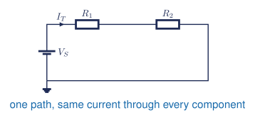
Opening any component stops current everywhere.
General rules
\[ I_k = I_T \tag{1}\]
\[ R_T = \sum_{k=1}^{n} R_k \tag{2}\]
\[ V_T = \sum_{k=1}^{n} V_k \tag{3}\]
\[ P_T = \sum_{k=1}^{n} P_k = V_T I_T \tag{4}\]
\[ I_T = \frac{V_T}{R_T} \tag{5}\]
\[ V_k = I_T R_k \tag{6}\]
How sigma notation works
\[ R_T=R_{eq}=\sum_{k=1}^{n}R_k=R_1+R_2+\cdots+R_n \tag{7}\]
\[ V_T=\sum_{k=1}^{n}V_k=V_1+V_2+\cdots+V_n \tag{8}\]
| Symbol | Meaning |
|---|---|
| \(R_T\) or \(R_{eq}\) | total or equivalent resistance |
| \(R_k\) or \(V_k\) | the value at position \(k\) |
| \(k\) | the index variable; it changes through \(1,2,3,\ldots,n\) |
| \(n\) | the fixed last index; the sum stops here |
\(\Sigma\) means add each term while \(k\) runs from \(1\) to \(n\). The final expanded term is \(R_n\) or \(V_n\). Keep full calculator precision until the final answer.
\[ \sum_{k=1}^{n} V_k \overset{?}{=} V_T \tag{9}\]
Use Equation Equation 9 to check the voltage drops. Also check power ratings.
Practical pathway: find the wrong voltage drop
Core learning: complete the existing series-circuit questions first. Then follow the Tinkercad build and measurement tutorial to reproduce the three-resistor worked circuit.
Guided practice: calculate total current, each voltage drop, and total power. Simulate the same values, measure at least two drops and the series current, and complete the table.
| Quantity and location | Predicted | Simulated | Difference |
|---|---|---|---|
| Series current (mA) | |||
| Resistor 1 voltage (V) | |||
| Resistor 2 voltage (V) | |||
| Total power (mW) |
Independent challenge: one simulated drop does not match. Decide whether the likely cause is a resistor value, probe location, source value, or topology error. Change one thing at a time and verify that all voltage drops add to the source.
- A series circuit has one current everywhere.
- Review the voltage-sum check immediately above this activity.
- Stop the simulation, inspect
ΩversuskΩ, then measure from the two terminals of the same resistor.
Optional Python verification: use Notebook 2 for repeated series values or Notebook 4 to graph a changing resistance.
Reflection: Which check located the fault fastest, and why would matching simulated values still not prove the real component ratings are safe?
Worked solutions
Questions 2 and 4 are provided as student models. Complete the other questions independently using the same GUESS structure.
Given: \(V_T=15.0\,\mathrm{V}\), \(R_1=1.0\,\mathrm{k\Omega}\), \(R_2=2.2\,\mathrm{k\Omega}\), \(R_3=3.3\,\mathrm{k\Omega}\).
\[ R_T=R_1+R_2+R_3=6.5\,\mathrm{k\Omega} \tag{10}\]
\[ I_T=\frac{V_T}{R_T}=\frac{15.0\,\mathrm{V}}{6.5\,\mathrm{k\Omega}}=2.307692\ldots\,\mathrm{mA} \tag{11}\]
Using \(V_k=I_TR_k\) gives \(V_1=2.307692\ldots\,\mathrm{V}\), \(V_2=5.076923\ldots\,\mathrm{V}\), and \(V_3=7.615385\ldots\,\mathrm{V}\).
Final answers: \(R_T=6.5\,\mathrm{k\Omega}\), \(I_T=2.3\,\mathrm{mA}\), \(V_1=2.3\,\mathrm{V}\), \(V_2=5.1\,\mathrm{V}\), \(V_3=7.6\,\mathrm{V}\), and \(P_T=35\,\mathrm{mW}\).
Check: Use the unrounded values: \(V_1+V_2+V_3=15.0\,\mathrm{V}\).
Given: a \(6.0\,\mathrm{V}\), \(80\,\mathrm{mA}\) lamp on a \(9.0\,\mathrm{V}\) source.
\[ V_R=V_T-V_L=9.0\,\mathrm{V}-6.0\,\mathrm{V}=3.0\,\mathrm{V} \tag{12}\]
\[ R=\frac{V_R}{I}=\frac{3.0\,\mathrm{V}}{80\times10^{-3}\,\mathrm{A}}=37.5\,\Omega \tag{13}\]
\[ P_R=V_RI=(3.0\,\mathrm{V})(80\times10^{-3}\,\mathrm{A})=0.240\,\mathrm{W} \tag{14}\]
Final answer: the calculated value is \(37.5\,\Omega\). Choose the next common 5% value, \(39\,\Omega\), rated for at least \(0.5\,\mathrm{W}\).
Key note: A \(0.25\,\mathrm{W}\) resistor is too close to the calculated \(0.240\,\mathrm{W}\) load.