Linear Algebra for Circuits
You will turn node or loop equations into a two- or three-variable system and solve it using elimination, matrices, or software. The method finds several unknown currents or voltages at the same time.
Used in college or university: Linear algebra, numerical methods, circuits, structures, process models, and control. [28, Chs. 9, 12]
Where you see it: A technician can model several currents in a car wiring network at once. A robotics engineer uses the same mathematics for sensor networks, motor currents, and control models.
Use the ground symbol as the 0 V reference before writing node or loop equations. The diagrams place higher-voltage nodes above ground and show the long battery line as positive so the equation signs match the schematic.
Class materials
- Teaching slides
- Make a copy of the current student problem set
- TEJ Electronics Quick Reference
- Grob Chapter 9: Kirchhoff’s Laws for forming the circuit equations
- Grob Problems Manual for Chapter 9 practice
- Teacher answers: restricted
A system of equations
Do not force the GUESS method onto a simultaneous system. Use this sequence: define the variables, write the circuit equations, put them in standard or matrix form, solve, and verify by substitution.
Each independent Kirchhoff loop gives one equation. Write every equation in the same variable order:
\[ \begin{aligned} a_{11}x_1 + a_{12}x_2 &= b_1 \\ a_{21}x_1 + a_{22}x_2 &= b_2 \end{aligned} \tag{1}\]
The same system is
\[ \underbrace{ \begin{bmatrix} a_{11} & a_{12} \\ a_{21} & a_{22} \end{bmatrix}}_{A} \underbrace{ \begin{bmatrix} x_1 \\ x_2 \end{bmatrix}}_{\mathbf{x}} = \underbrace{ \begin{bmatrix} b_1 \\ b_2 \end{bmatrix}}_{\mathbf{b}} \tag{2}\]
In compact form:
\[ A\mathbf{x}=\mathbf{b} \tag{3}\]
Solve and check
Use substitution or elimination for a small system. Use a simultaneous-equation or matrix solver for a larger system. Keep the variable order and units consistent, then substitute the answer into the original equations or calculate the residual:
\[ \mathbf{r}=A\mathbf{x}-\mathbf{b} \tag{4}\]
\[ \mathbf{r}\approx\mathbf{0} \tag{5}\]
A large residual can flag a wrong sign, wrong measurement, or wiring fault.
Three unknowns
Worked solutions
On the course calculator, the Casio fx-991ES PLUS C, press MODE, then 5 for EQN. Press 1 for two unknowns or 2 for three unknowns. Enter each coefficient in equation order and press = after every value; after the final coefficient, each additional = displays the next solution. This sequence is verified against the official Casio fx-991ES PLUS C equation guide.
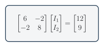
Enter the rows \((10,-4,6)\) and \((-4,12,3)\).
\[ \begin{bmatrix} 10 & -4 \\ -4 & 12 \end{bmatrix} \begin{bmatrix} I_1 \\ I_2 \end{bmatrix} = \begin{bmatrix} 6 \\ 3 \end{bmatrix} \tag{6}\]
Final answers: \(I_1=0.808\,\mathrm{mA}\) and \(I_2=0.519\,\mathrm{mA}\).
Substitution into both original rows gives a residual of approximately zero.
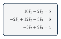
Enter the coefficient rows \((10,-2,0,5)\), \((-2,12,-3,6)\), and \((0,-3,9,4)\). The zeros keep the variable columns aligned.
Final answers: \(I_1=0.657\,\mathrm{mA}\), \(I_2=0.786\,\mathrm{mA}\), and \(I_3=0.706\,\mathrm{mA}\).
Substitute the three currents into all three original rows to check the solution.
Practical pathway: audit a computational solution
Core learning: solve one assigned system using the established variable-and-equation workflow. Then download Notebook 3: Kirchhoff Systems, click OPEN JUPYTERLITE NOW, choose Upload Files, and double-click the downloaded notebook. Use the step-by-step JupyterLite instructions if needed.
Guided practice: enter the same coefficient order in every matrix row. Compare the notebook result with the manual or calculator result, then calculate the residual for each original equation.
| Evidence | Manual or calculator | Python | Difference or residual |
|---|---|---|---|
| Unknown 1 (mA) | |||
| Unknown 2 (mA) | |||
| Unknown 3 (mA), if used | |||
| Largest equation residual (V) |
Independent challenge: introduce one realistic transcription error, predict how the residual or circuit check will respond, then design a procedure that finds the wrong row without seeing a worked solution.
- Print the variables and units beside the matrix.
- Compare one row at a time with the original equation, not with another matrix copy.
- Substitute the computed currents into a separately typed KCL or KVL check so the same transcription error is less likely to appear twice.
Optional extension: simulate or measure the original circuit when the available tool can represent it faithfully. A matching experiment increases confidence in the model; the numerical solve alone does not validate the schematic.
Reflection: Which independent check was least likely to repeat the same error as the matrix entry?