Background
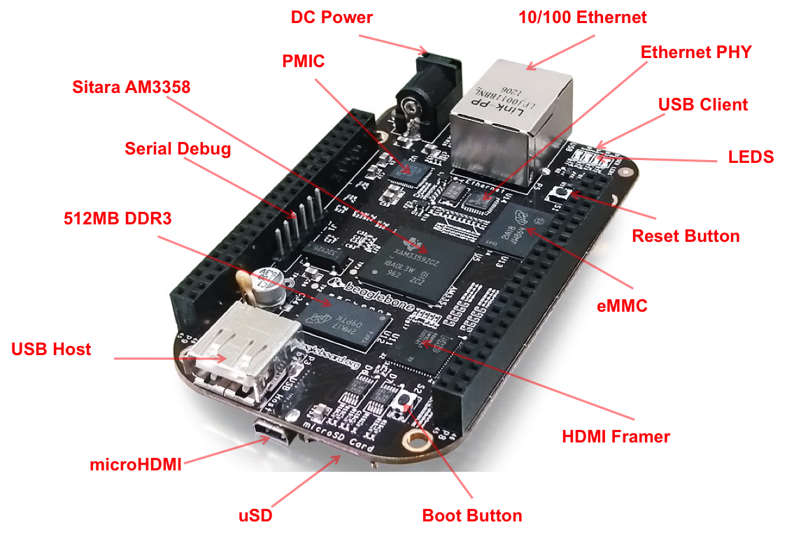
As previously mentioned my fourth year design project (FYDP) involves building an energy storage system (ESS) using repurposed electric vehicle (EV) batteries. After individual battery cells are removed from the large high voltage EV battery, the first step the project is testing the battery cells to see if they are “healthy” and ready to use. This means we have to charge and discharge the cells while monitoring both the voltage and the temperture. We are planning on using a BeagleBone Black (BBB) as our microcontroller (show below), and have to pick sensors to measure voltage and temperature.

Project Scope
Since we are running lean, our goal is to try and get to stage of safetly changing and discharging the battery autonomously as quickly. This means for our minimal viable product (MVP), we had the following goals:
- Label every battery cell with a unique identifier, and keep log of all tests and data.
- Be able to autonomously charge the battery. This means be able to stop charging when either the battery reaches 50 degrees C or the voltage accross the battery cell exceed 7.2 V.
- Constantly measure voltage accross the battery over time
- Constantly measure the temperature of the battery over time
- Be able to autonomously discharge the battery by pressenting a simple resistive load
These are a couple of stretch goals:
- Steam data online
- Test Multiple Cells
- Coloumb counting
Let’s start with choosing the sensors and figuring out how to take measurements.
Instrumentation and Measurement
Measuring Voltage
Measuring voltage using a BBB is simple: we can simply use the analog input pins on the BBB to measure voltage. The first issue is that according the the BBB documentation, to safetly read analog values, the input voltage to the analog to digital convert (ADC) is limited to 1.8V. This means that the input voltage must be properly limited to ensure the safe operstion. To achieve this, a simple voltage divider can be used (by apply Ohm’s Law \(V = I R\)).
Voltage Divider
Based on Ohm’s Law, the circuit above can be simplified to \(V_o= \frac{I R_2}{I ( R_1 + R_2 ) } V_{in} \), and finally to this form:
\[V_o=\frac{R_2}{R_1+R_2}V_{in} \]
Now given a desired \(V_o\) and known \(V_{in}\), \(R_1\) and \(R_2\) can be solved for. We wanted the ability to read up to 30V (including contingency), and still limit the voltage to the BBB to 1.8 V. Here we use \(V_{in}=30V\) and \(V_o=1.8V\). By setting the smaller resistor \(R_2\) in this case) to \(10k\Omega\), one can solve \(R_1=160k\). Note, resistor come in standard resistances, so one must round to ensure the limits are sets correctly. In this example, \(R_1\) should be rounded up not down. Why? Think about how the voltage devider works.
How to not drain battery while measuring
The issue with this method is that with a total resistance \(R1 + R2 = 180K\Omega\), then the total current drawn \(I_{total} ={V_{in}} / R_{total} = 30V / 180k\Omega = 1.66\times10^{-4} A\) While this is a very smal current drawn, slowly by slowly it will be drain the battery. The way to reduce this effect is to increase the resistors, to the \(M\Omega\) range, such at that current being drawn will be very low. The issue with this is that there will not be a minimum current which exceeds the leakage current in a pin. In short, the current can not be too small or it will cause measurement issues. But can this be solved? Yes! The trick is to add a small capacitor in parallel with the \(R_2\) resistor. This improves the readings of the voltage out, yet enables us maintain a very low current.
Temperature Sensors
There exist many different types of temperature sensors which function in different ways. The choice of the temperature sensor and implmentation will be talked about in the next blog post!
